博文

目前显示的是 五月, 2025的博文

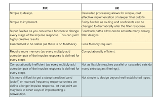
What are the advantages and disadvantages of FIR and IIR filters?
图片
  FIR (Finite Impulse Response) and IIR (Infinite Impulse Response) filters are the two main types of digital filters used in signal processing. Each has its advantages and disadvantages depending on the application.  FIR vs. IIR Filter Comparison Feature FIR Filters IIR Filters Impulse Response Finite (settles to zero in finite time) Infinite (theoretically never ends) Stability Always stable (if implemented correctly) May become unstable due to feedback Phase Response Can be designed to have linear phase Generally non-linear phase Implementation Complexity Requires more coefficients for sharp filters Efficient with fewer coefficients Design Flexibility Easier to design with exact specifications More difficult to design with precise specs Computational Load Higher (more multiplications/additions) Lower (more efficient for real-time use) Sensitivity to Quantization Less sensitive More sensitive (feedback path affected) Applications Audio, communications, systems needing ...

What is interrupt in microcontroller?

图片
  An interrupt in a microcontroller is a signal or event that temporarily halts the normal execution flow of your program so the microcontroller can respond to an urgent task or event immediately . Simple Definition: An interrupt is like someone tapping your shoulder while you're working — you pause what you're doing , handle the urgent matter, then go back to your original task . How It Works: The MCU is running your main program (called the main loop). An interrupt event occurs (e.g., a button press, timer overflow, data received). The MCU pauses the main program. It jumps to a special function called an Interrupt Service Routine (ISR) or interrupt handler . Once the ISR is done, it returns to where it left off in the main program. Types of Interrupts: External Interrupts – Triggered by changes on input pins (e.g. button press). Timer Interrupts – Triggered by internal timers reaching a value. Peripheral Interrupts – Triggered by e...

What are the steps to develop firmware for an SoC?

图片
 Developing firmware for a System on Chip ( SoC ) is a structured process that bridges hardware and software. The steps vary based on the SoC and target application, but here is a general roadmap : 1. Requirements & Planning  Define the product’s functionality and system requirements.  Choose the appropriate SoC (based on CPU, peripherals, memory, power, etc.).  Obtain datasheets, reference manuals, and SDKs/toolchains from the SoC vendor.  Identify interfaces (UART, I2C, SPI, USB, etc.) and external components ( sensors , memory, radios). 2. Hardware Setup  Build or acquire the development board or custom hardware.  Ensure access to: JTAG/SWD debug ports UART for logs Power monitoring (if needed) 3. Toolchain Setup  Install compiler and IDE/toolchain (e.g. GCC + Make , Keil , IAR , Segger Embedded Studio , STM32CubeIDE , etc.).  Setup: Debugger drivers (e.g., ST-Link, J-Link) Flashing ...

Detailed explanation of TIM timed interrupt in STM32

图片
 A TIM timed interrupt in STM32 (using a general-purpose timer ) is one of the most powerful features in real-time embedded systems. It allows the microcontroller to perform specific tasks at precise time intervals, independent of main code execution .  What Is a TIM Timed Interrupt? A TIM interrupt is an event triggered by a timer peripheral (e.g., TIM2 , TIM3 , etc.) when it counts to a specified value . You can configure this to fire periodically, for example, every 1 ms or every 1 second .  Use Cases Blinking LEDs at a fixed rate Running a real-time scheduler Sampling sensors at fixed intervals Generating PWM signals (with interrupts)  Key Registers in TIM Register Role PSC Prescaler (divides timer clock) ARR Auto-reload register (sets period) CNT Current counter value DIER Interrupt enable register SR Status register (flags) CR1 Control register (start/stop)  Basic Timing Formula To generate an interrupt every T seconds : ini ...

How to add a GPS sensor to ESP32 for Wokwi?

图片
 To add a GPS sensor to an ESP32 in Wokwi , follow these steps:  Step-by-Step Guide 1. Open Wokwi Go to https://wokwi.com and start a new project with ESP32 . 2. Add the GPS Module Wokwi supports a virtual "NEO-6M GPS module" . You can add it in the diagram.json file or via the visual editor. Example diagram.json : json { "version" : 1 , "author" : "you" , "editor" : "wokwi" , "parts" : [ { "type" : "wokwi-esp32-devkit-v1" , "id" : "esp32" , "top" : 100 , "left" : 50 } , { "type" : "wokwi-gps" , "id" : "gps1" , "top" : 100 , "left" : 250 } ] , "connections" : [ [ "gps1:TX" , "esp32:RX2" , "green" , [ "v0" ] ] , [ ...

What is the difference between using an internal vs. external oscillator in STM32?

图片
 Using an internal vs. external oscillator in an STM32 microcontroller affects clock accuracy, stability, cost, power consumption, and design complexity. Here's a comprehensive breakdown of the differences: 1. Internal Oscillator (e.g., HSI, MSI, LSI) What it is: Built-in oscillator in the STM32 chip. Common types: HSI (High-Speed Internal): Typically 16 MHz MSI (Multi-Speed Internal): Used in STM32L series (100 kHz to 48 MHz) LSI (Low-Speed Internal): ~32 kHz, for watchdogs or low-power timing Advantages: Feature Description No external components Reduces BOM cost and PCB complexity Lower power Especially MSI for low-power modes Faster startup time Ideal for wake-up from sleep modes Space saving No external crystal required Disadvantages: Feature Description Lower accuracy ±1% to ±3% frequency variation (temperature, voltage dependent) Not suitable for USB USB and precise UART require exact timing Limited stability May drift over time and temperatu...

How do I optimize code for faster execution?

图片
 Optimizing code for faster execution—especially in embedded systems like with STM32 —means improving how efficiently the CPU runs your program. This involves algorithmic improvements , compiler settings , hardware-aware coding , and memory access optimization . Here’s a breakdown of strategies you can apply:  1. Algorithmic Optimization (Most Important)  Use efficient algorithms and data structures: Replace O(n²) loops with O(n log n) when possible (e.g., sorting). Minimize nested loops and redundant computations. Cache reused calculations.  Bad: c for ( int i = 0 ; i < N; i++) for ( int j = 0 ; j < N; j++) result += array [i] * array [j];  Better: c int sum = 0 ; for ( int i = 0 ; i < N; i++) { sum += array [i]; } result = sum * sum;  2. Use Compiler Optimization Flags If you're using GCC (like in STM32CubeIDE) : -O0 – No optimization (default for debugging). -O1 , -O2 , -O3 – Increasing levels of o...

What is the recommended voltage range for powering an Arduino Uno?

图片
 The recommended voltage range for powering an Arduino Uno depends on how you're supplying power: 1. Via USB Port Voltage: 5V regulated The USB port directly provides 5V , regulated by your computer or USB charger. Safe and preferred for most use cases. 2. Via Barrel Jack (External Power Supply) Recommended Input Voltage: 7V to 12V Absolute Range: 6V (min) to 20V (max) Internally, this goes through the onboard voltage regulator which converts it to 5V. Ideal voltage: 9V DC adapter (center-positive) is most commonly recommended. Avoid: < 7V: May not regulate to stable 5V, especially under load. 12V: Causes excess heat in the voltage regulator, can damage the board. 3. Via VIN Pin Same as the barrel jack: 7V to 12V recommended , 6V to 20V allowed . This pin feeds the voltage regulator. 4. Via 5V Pin Exactly 5V regulated  Use with caution : Bypasses the onboard regulator and protection circuits. Should only...