博文

目前显示的是 十二月, 2024的博文

How to Using ADC Scan Mode with DMA in STM32F407

图片
 In STM32F407 , the ADC (Analog-to-Digital Converter) can be used in Scan Mode with DMA (Direct Memory Access) to efficiently sample multiple analog channels without CPU intervention. 📚 1. Overview ADC Scan Mode: Allows the ADC to scan through multiple channels sequentially. DMA (Direct Memory Access): Automatically transfers ADC conversion results from ADC data registers to a specified memory location. Use Case Example: Reading multiple analog sensors (e.g., temperature, light, voltage sensors). ⚙️ 2. Hardware Setup Microcontroller : STM32F407 (e.g., STM32F4 Discovery board) Analog Inputs: Connect analog sensors to ADC channels (e.g., PA0, PA1, PA2) . Power Pins: Ensure VREF+ is connected to 3.3V and VREF- to GND. DMA Channel: DMA2 Stream0 (ADC1). 🛠️ 3. Configuration Steps Step 1: Enable Peripheral Clocks Enable clocks for ADC1 , GPIOA , and DMA2 . Step 2: Configure GPIO Pins for ADC Set GPIO pins (e.g., PA0, PA1, PA2 ) as analog mode . Step 3: Configure ADC in Scan ...

What is the anti-interference ability of STM32F407 serial port?

图片
 The STM32F407 microcontroller features multiple USART (Universal Synchronous Asynchronous Receiver Transmitter) peripherals, widely used for serial communication. Its anti-interference ability depends on both hardware design and software configuration . Below are key factors affecting its anti-interference capability: 🛡️ 1. Hardware Anti-Interference Design Signal Integrity: Use shielded cables for UART communication over long distances. Keep TX (Transmit) and RX (Receive) lines away from high-frequency or high-current traces. Proper Grounding: Ensure common ground (GND) between devices. Use star grounding topology to reduce noise loops. Pull-Up/Pull-Down Resistors: Use pull-up or pull-down resistors on idle UART lines to prevent floating states. Decoupling Capacitors: Place 0.1µF and 10µF capacitors near the power pins of the STM32F407 to filter high-frequency noise. Isolation Circuits: Use opto-isolators or RS-485 differential transceivers for long-distance commun...

The difference between Microcontrollers and Microprocessors

图片
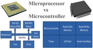
 Microcontrollers and microprocessors are both essential components in embedded systems and computing devices, but they differ significantly in terms of architecture, functionality, and applications. 📚 1. Definition Microcontroller (MCU): A compact integrated circuit (IC) that contains a CPU , memory (RAM, ROM/Flash) , and peripheral interfaces (GPIO, ADC, timers) on a single chip . Designed specifically for embedded applications . Microprocessor (MPU): A CPU (Central Processing Unit) integrated into a single chip, designed to execute instructions and perform calculations. External components (RAM, ROM, I/O controllers) are required to build a complete system. ⚙️ 2. Architecture Feature Microcontroller (MCU) Microprocessor (MPU) Components CPU, RAM, ROM, I/O ports, peripherals integrated CPU only (requires external peripherals) Memory On-chip RAM and Flash memory External RAM, ROM required Bus Width Typically 8-bit, 16-bit, 32-bit 32-bit, 64-bit Clock Speed Moderate (e.g., 8 M...

How to Make an Alarm System on an FPGA?

图片
 Creating an alarm system on an FPGA involves designing a digital logic circuit that responds to specific conditions (e.g., a button press, sensor signal, or threshold value). Below is a step-by-step guide to implement a basic alarm system using VHDL or Verilog , with an example using a buzzer or LED indicator as the alarm output. 1. Define System Requirements Trigger Condition: A button press, a sensor (e.g., temperature, motion, light), or a pre-set threshold. Alarm Output: LED blinking, buzzer sound, or both. Reset Mechanism: A button or condition to turn off the alarm. FPGA Board: Select a board (e.g., Xilinx Spartan-6, Virtex-4 , or similar). Example Scenario: Input: A push-button acts as the alarm trigger. Output: A blinking LED and buzzer sound. 2. Design the Alarm Logic State Diagram: Idle State: Waiting for trigger signal. Alarm State: When triggered, activate LED and buzzer. Reset State: Return to idle when reset signal is detected. 3. Write HDL Code VHDL Ex...

How To Connect Stm32 To PC?

图片
Connecting an STM32 microcontroller to a PC typically involves using a communication interface such as USB , UART (serial) , SPI , or I2C . The most common and straightforward method is through USB or UART . Below, I’ll explain how to connect your STM32 to a PC using these methods. Method 1: Using USB (Direct Connection via Virtual COM Port) Many STM32 boards, such as the STM32 Nucleo or STM32 Discovery series, have a built-in USB-to-serial interface, which allows you to communicate with your PC via a virtual COM port . Steps for Connecting via USB: Use a USB Cable : If your STM32 board has a built-in USB interface (e.g., STM32 Nucleo boards ), simply use a micro-USB or USB-C cable to connect the board to your PC. Install Drivers (if required) : Some STM32 boards (e.g., those with ST-Link or USB to UART interfaces) might require drivers to be installed on your PC. Visit the STMicroelectronics website and download the appropriate ST-Link drivers or Virtual COM Port (VCP) dri...

What Can I Do With An FPGA Board​?

图片
 An FPGA ( Field-Programmable Gate Array ) board is a powerful tool for hardware design and prototyping. Unlike fixed-function chips (like CPUs or GPUs), an FPGA allows you to program its hardware to perform a wide range of tasks, offering extreme flexibility and parallelism. Below are some of the things you can do with an FPGA board: 1. Custom Hardware Design One of the primary uses of an FPGA is to create custom digital circuits. You can design your hardware functions from scratch, tailoring it specifically to your needs. FPGAs are programmable logic devices, so you can design and implement digital circuits such as: Arithmetic Units: Design custom arithmetic circuits like adders, multipliers, dividers, etc. Digital Signal Processors ( DSPs ): Implement DSP algorithms for filtering, FFTs, or signal analysis. Custom Memory Interfaces: Design your own interfaces for different types of memory (RAM, Flash, etc.). Control Systems: Design complex control systems for robotics, au...

Can Raspberry Pi 4 run ARM64 OS?

图片
 Yes, the Raspberry Pi 4 can run an ARM64 (64-bit) operating system . In fact, it’s fully capable of running a 64-bit OS due to its Broadcom BCM2711 processor , which supports ARM Cortex-A72 (ARMv8-A architecture) . 📌 Why Choose a 64-bit OS? Better Performance : Improved performance for certain applications. Larger Memory Support : Access to more than 4GB of RAM (useful for 8GB Raspberry Pi 4). Improved Compatibility : Required for some software packages and Docker containers that only support ARM64. 📌 Supported 64-bit Operating Systems for Raspberry Pi 4 Raspberry Pi OS (64-bit) — Officially supported. Ubuntu Server / Ubuntu Desktop (64-bit) Manjaro ARM (64-bit) Debian ARM64 Kali Linux ARM64 🚀 Recommended OS for Raspberry Pi 4 For most users, Raspberry Pi OS 64-bit is the best choice due to its stability and official support. 📌 How to Install a 64-bit OS on Raspberry Pi 4 Download the OS Image: From the official Raspberry Pi website . Flash the OS Image: Use tools like Ra...

STM32F103C6T6 pin arrangement instructions

图片
  The STM32F103C6T6 is a 48-pin microcontroller packaged in LQFP. Here is the detailed pin arrangement instructions: Power Pins VDD_4  and  VSS_4 : These are the digital power supply and ground pins respectively. They provide power and the reference ground for the digital components of the microcontroller. VDDA  and  VSSA : These pins supply power and the ground reference for the analog components such as the ADC, oscillators, etc. within the microcontroller. VBAT : This pin is connected to an external backup battery. It provides power to the RTC (Real-Time Clock) and backup registers when the main power supply is off, ensuring that the RTC continues to run and the backup data is retained. Oscillator Pins OSC_IN  and  OSC_OUT : These are the input and output pins for the main oscillator. Typically, an external crystal oscillator is connected between these two pins to provide the system clock source for the microcontroller. In some cases, these pins ca...

STM32F105 Serial Port Configuration Method

图片
 The STM32F105 microcontroller features up to 5 USART peripherals (USART1–USART5) for serial communication. These USART peripherals can be configured for both asynchronous (UART) and synchronous communication. Below is a step-by-step guide to configure the serial ports on the STM32F105: 1. Clock Configuration The USART peripherals are connected to APB1 and APB2 buses: USART1 : Connected to APB2 bus (max clock: 72 MHz) USART2–USART5 : Connected to APB1 bus (max clock: 36 MHz) Steps to Enable the Clock : Enable the peripheral clock for USART and GPIO ports in the RCC (Reset and Clock Control) register. c RCC_APB2PeriphClockCmd(RCC_APB2Periph_USART1 | RCC_APB2Periph_GPIOA, ENABLE); // Enable clock for USART1 and GPIOA RCC_APB1PeriphClockCmd(RCC_APB1Periph_USART2, ENABLE); // Enable clock for USART2 2. GPIO Configuration Each USART peripheral has dedicated Tx (Transmit) and Rx (Receive) pins, which need to be configured as Alternate Function Push-Pull ...